Update: Consumer Sous Vide machines have really dropped in price since I made my sous video machine. I now recommend an Anova Sous Vide instead of making one.
You probably thought I was going to throw some hot rocks into a pool of water, didn’t you 🙂 Well if you haven’t heard of Sous Vide before, its pretty much the ultimate keto cooking tool. The basic idea is that you vacuum seal food into a bag and place it into a hot water bath for a period of time. The temperature of the water bath is maintained at a steady temperature which is the desired finishing temperature for the meat. This is how restaurants get perfectly pink steak from side to side without burning it. They simply set the Sous Vide to 140 degrees F and bam, medium steak. The only problem is that even the lowest end consumer Sous Vide machines go for a lot of dough. So, what’s a man to do, build my own of course! I started my journey by reading the Make: Sous Vide Immersion Cooker but I ended up varying quite a bit on the components and design. I went through two earlier revisions but I think this latest one is good enough to share with the world.
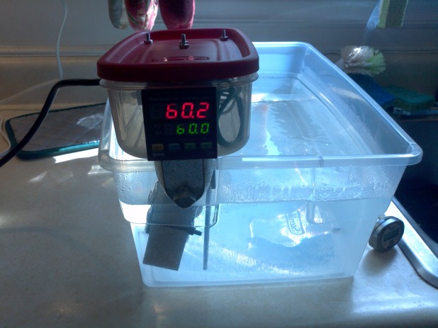
As you can see, the unit is contained in a standard Rubbermaid container and clamps to a storage container where the water goes. You set the temperature on the controller and off you go!
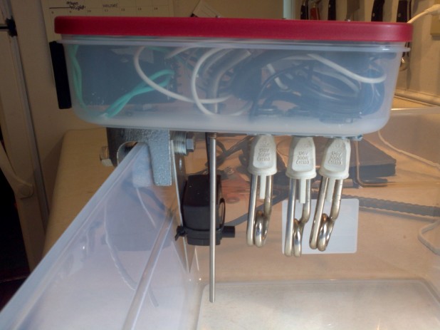 Here is a side view of the unit with no water. From left to right, you have the mounting bracket, the pump, then the temperature probe, followed by three heating elements. Now that you’ve seen the goods, lets get on to how to build your own!
Caveman Sous Vide
Parts:
- PID Controller – MYPIN TA4 – SSR – $26.09
- Solid State Relay – SSR-25DA – $9.20
- Thermocouple – $6.19
- Water Heater – NORPRO 559 – $7.39 x 3
- Screw Terminal – $6.57
- Fountain Pump – Little Giant 566713 – $18.35
- Container – Rubbermaid 7M71 – $7.99
- Switch – $4.00 ( Radioshack Link )
- 16 Qt Plastic Storage Bin (Homedepot, Amazon or Bed Bath and Beyond)
- Electrical Clamp Connectors – Halex 20511 – $6.31 ( Home Depot Link )
- Electrical Beam Clamp – $5.22 ( Home Depot Link )
- 2 – 3/8″ x 1/2″ Hex Bolt
- 3/8″ Washers
- 4 – #8 machine screws, washers and nuts
- Approx. 5″ x 1″ aluminum rectangular bar
Equipment:
- Soldering Iron – Weller SP40L
- Drill
- Drill Bit Set
- 1/2″ Paddle Bit – Electrical Clamps
- 7/16″ Paddle Bit – Switch
- #16 Drill Bit (0.177) – #8 Machine Screws
- #X Drill Bit (0.397) – 3/8″ Hex Bolts
- Phillips Screwdriver
- Wire Strippers
- Dremel with Cutting Attachment
Consumables:
- Resin Core Solder (Not Lead Free)
- 14 Gauge Wire (Multiple Colors)
- Heat Shrink – Assorted Sizes
- Zip Ties
- Electrical Wire Nuts
Disclaimer: This project involves electricity, power tools and water. If you don’t feel comfortable combining all three of these, I would just buy a commercial machine. I am in no way responsible if you hurt yourself and you should undertake this project at your own risk!
So my main goal in making this Sous Vide machine was for it to be as easy as possible for the average hobbyist to make. I did the whole design with no custom parts and everything can be bought from Amazon and shipped directly to your house. In reality, my version included some items I already had and some of them I bought from either Home Depot or Radioshack. Things like the electrical clamps and small hardware are probably cheaper at a hardware store and you should go there for those items. Let’s get started!
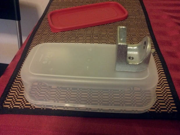 The first step is to attach the electrical beam clamp to the bottom of the container. It took me a while to find a suitable way to mount the container to the water vessel but when I saw this in the hardware store I was ecstatic! It can hold 750 lbs and comes with all the proper mounting orientations we need built in. Place the mount as shown with the edge up against the lip and centered. Then mark the center of the whole and drill it out with a #16 or close drill. You can either secure the mount on now with a 3/8″ hex bolt and washer or wait. I should also note that if you can’t find hex bolts short enough to not hit the container, buy a longer one and cut it with the dremel.
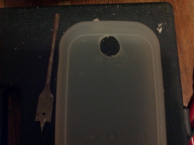 Next cut the three holes for the heaters. Make sure to space them out enough so that the nut can secure on the other end. Roughly put them in the center line of the container. In an ideal scenario, all of the heaters are aligned and the pump pushes the water through their aligned holes. Use the paddle bit to make the whole but you might need to expand it a little with a dremel to make it fit.
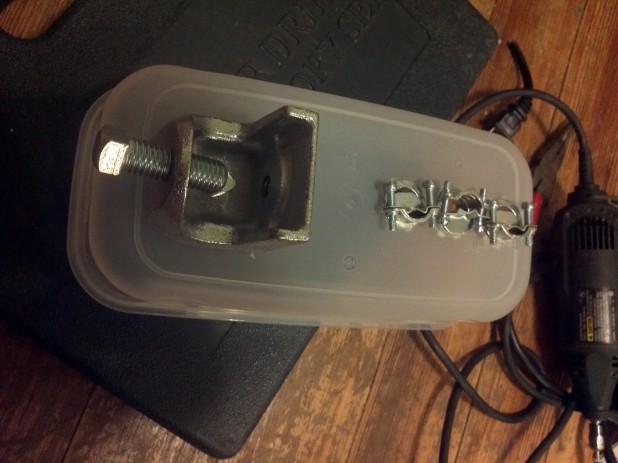 Here is a picture with the three clamps installed. It really was a moment of genius when I found these clamps. There really is no good way to hold these stupid heaters because they are just plastic with no retention mechanism. However, they do have a little lip on them and it perfectly fits into the cable clamp. Originally I was just going to grab the wire coming off the heater but they held even better on the lip.
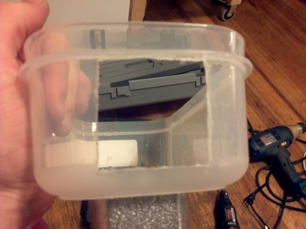 Cut out a hole for the controller. With this container the PID controller fits perfectly under the lip. Trace it and then very carefully cut it out with the dremel.
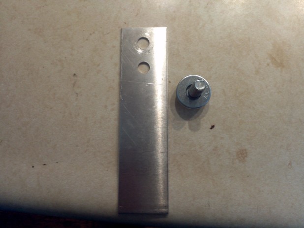 The aluminum rectangular bar is for the pump. Technically the pump has suction cups on the back of it but they are pretty miserable. Also, this keeps the pump in the exact position you want. Measure twice and cut once, hence the two drill holes … You’ll end up zip tieing the pump to this bar after it gets bolted to the same clamp that holds the container.
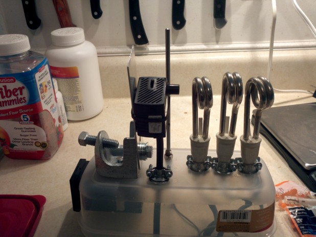 Here is the finished bottom. Quite nice looking if I do say so myself 🙂 You can see that I ran another electrical clamp for the pump wire and I also installed the thermocouple.
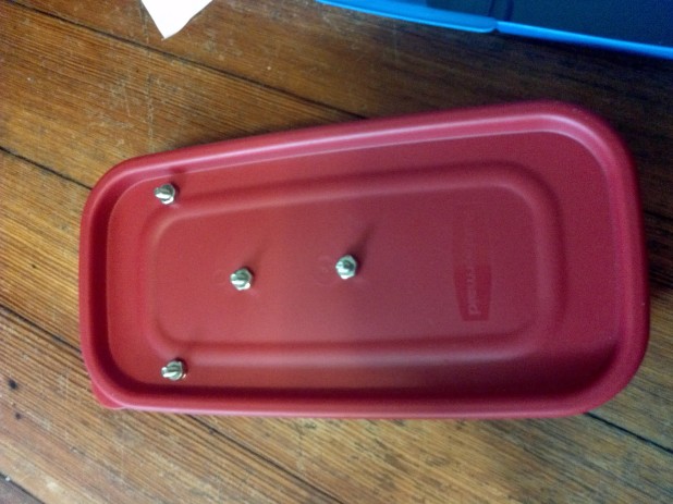
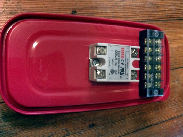 I put all of the electronics on the lid of the container. On the left is the SSR or solid state relay. Because the elements of the system can draw a lot of power, the PID controller actually only sends out a low voltage signal that then switches this SSR. This SSR is then capable of switching a much larger load. Basically the PID connects to this and it acts as a large switch for the heaters. The item on the right is a terminal strip and just makes wiring easier. To connect these, just use #8 screws with nuts and washers. I just marked them and drilled holes through the top.
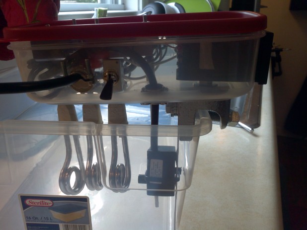 Here you can see the last container mod which is the power cable and the power switch. I originally bought a really cool switch from Amazon but it was rectangular and would have been near impossible to install. Instead I drove to Radioshack and picked up a simpler switch that can be installed with one drill hole. I also secured the power cord with the last of the five electrical clamps.
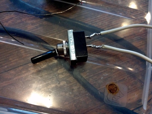 Most of the wiring is via screw terminal but the switch needs to be wired another way. You can do it however you want, twisting, duct tape, crimp connectors, whatever. However the correct way is to feed the wire through, then twist it, then solder it as shown. I specified leaded solder because simple, cheap soldering irons have problems with lead-free solder and this small amount of solder isn’t going to hurt anything.
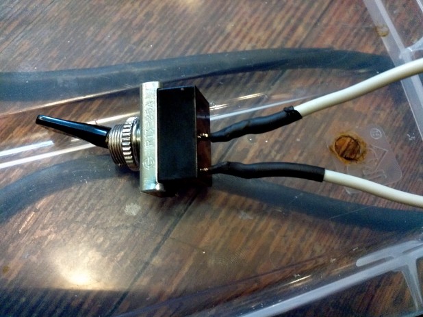 Again, you can do it anyway you want, but ideally it should be covered in heat shrink.
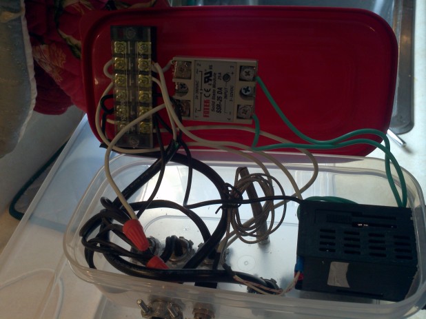 Here is the final wiring. I should note that rather than buy wire, I just took an old extension cord I had and ripped it apart. You then have 25 feet of wire designed for this purpose without having to buy anything expensive! Also, make sure to read the manual regarding your particular controller to make sure you wire it up properly. The theory with the wiring was that I put the hot side (black) on a switch and ran neutral to wherever it was needed. So when you hit the switch, it turns on the pump and the controller and makes half of the SSR live. Then the PID controller controls the SSR and can connect the hot to the neutral to complete the circuit for the heaters. The thermocouple then connects directly to the PID controller. NOTE: Make sure it is in water when you hit the power because these pumps and the heater will burnout if not submersed underwater.
Wiring Diagram:
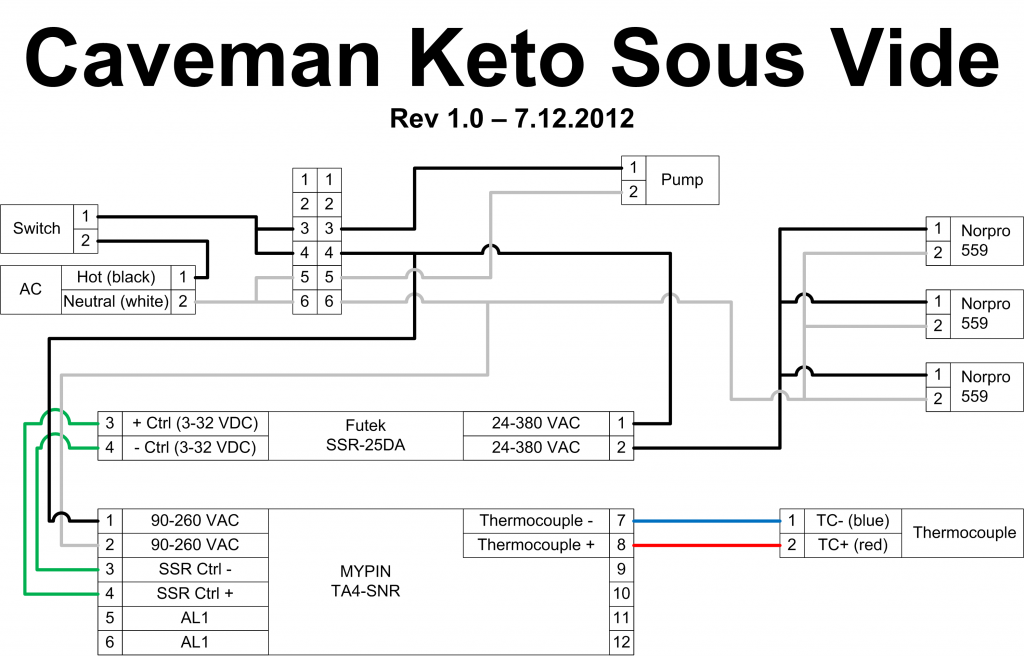 Well folks that’s it! I will likely be cooking a lot with this in the near future so check out my Sous Vide Recipe section and as time goes on I’ll post all of my vacuum cooking adventures!
Oh, and just for fun, here are some pictures of the earlier revs I went through before I settled on this one!
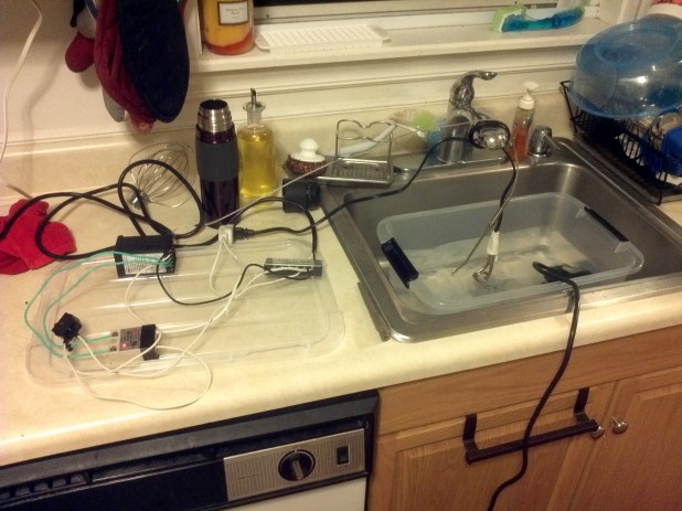 This was the very first test, I literally just wired it and used it in the sink.
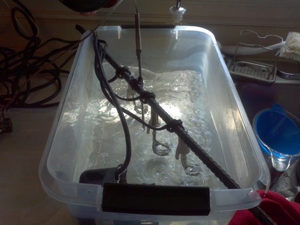 Rev 1.2 used a huge old pond pump I had and some rebar to hold the heaters. I left the house while cooking some eggs and they all exploded because of the power of the pump!
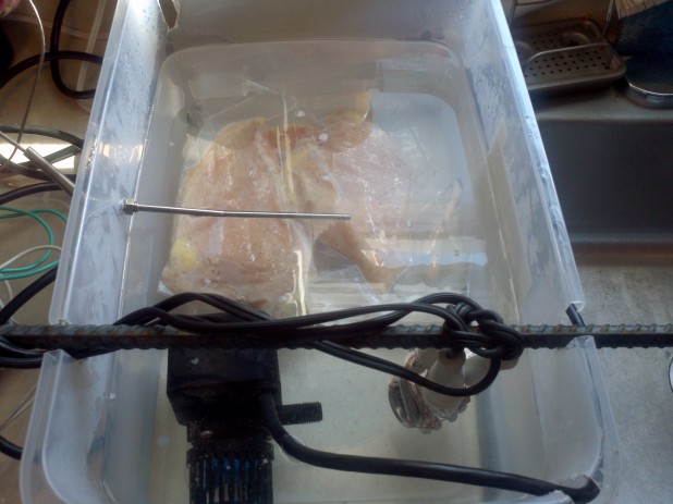 For rev 1.5 I did a tighter integration with more cooking space. I also put a filter on the pump to reduce its speed.
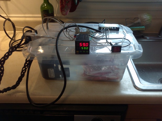 For rev 2.0, I attached all of the components to the lid. This was also the first time I attached the pump to the same switch. Prior I had to plug in the pump separately. This version worked well, and I used it a lot, but it isn’t portable and its completely built into this one container. It also was very hard to keep a consistent temperature with the lid on like this, the temperature would rise too much. Not to mention all the electronics were exposed.
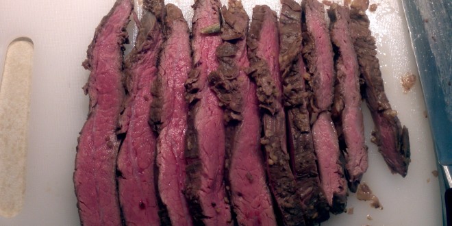
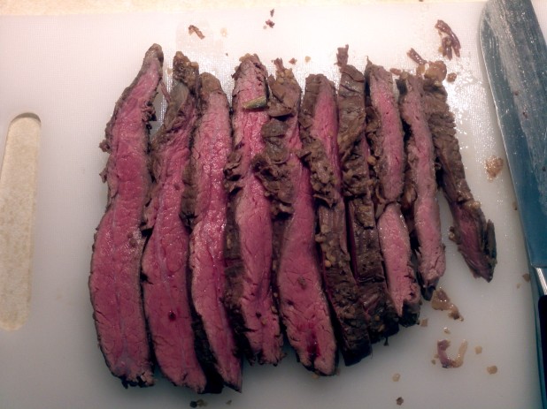
Well, thanks for reading this far! Here is some 24 hour cooked flank steak for your effort:
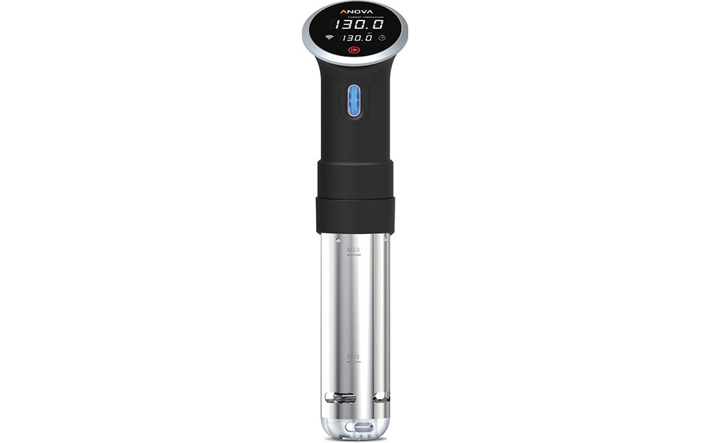 Anova Sous Vide Cooker Anova Sous Vide CookerSous Vide was one of my first forays into extreme stunt cooking. I made my own DIY Sous Vide machine but you can skip all that trouble and just pick up a commercial model. The prices have dropped dramatically and its insane how nice cuts like prime rib cooked for 10 hours come out! |
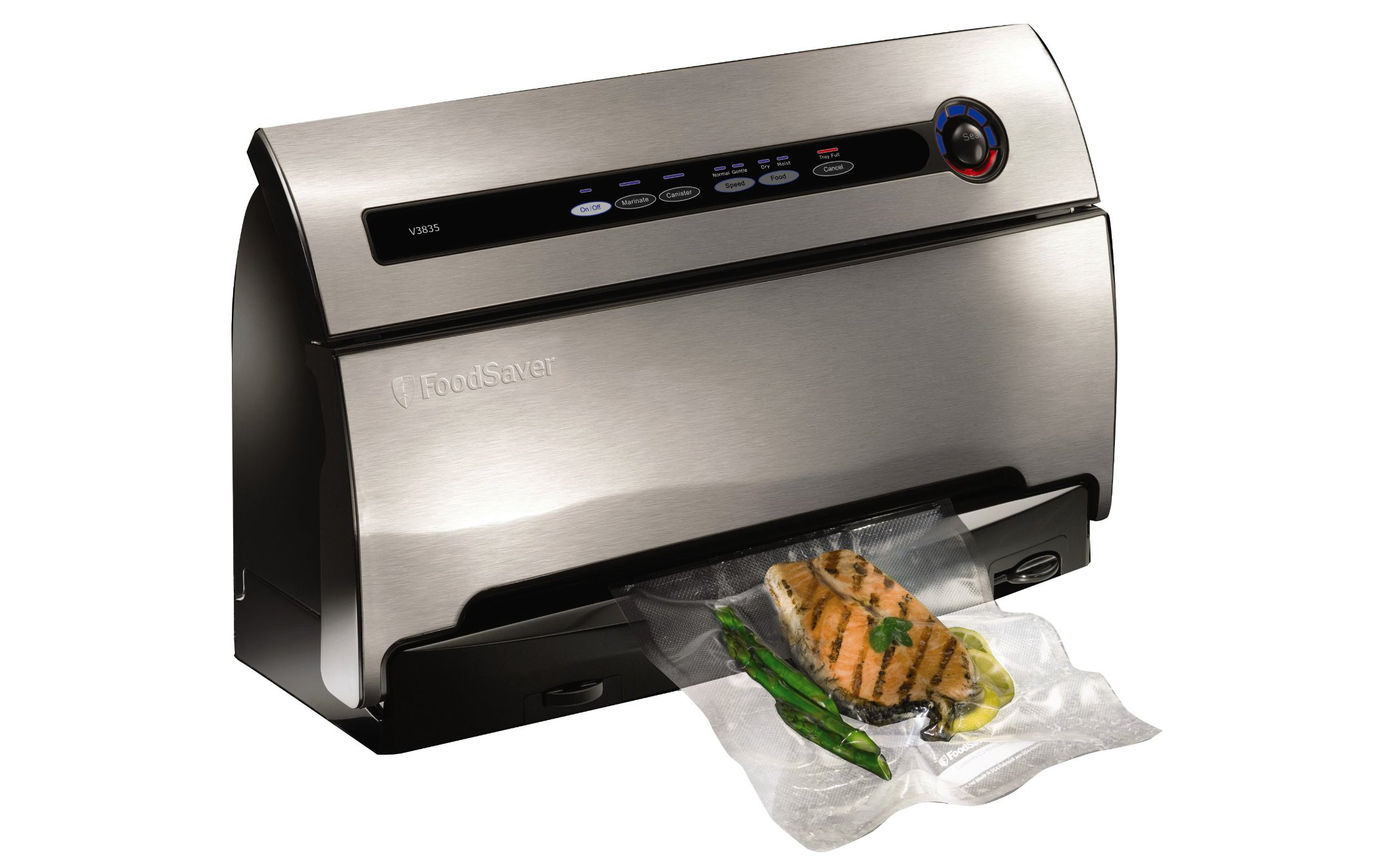 FoodSaver V3835 Vacuum Food Sealer FoodSaver V3835 Vacuum Food Sealer A Vacuum Sealer is more like an enabling technology in the CMK kitchen. Its necessary for a Sous Vide setup but once you get one you’ll find yourself resealing half eaten bags of pork rinds, or buying bulk meats at BJs and freezing them in perfectly sealed, pre-portioned bags. |
 FoodSaver Bag Combo Pack FoodSaver Bag Combo PackPerfect companion for any of your Sous Vide needs! Either cut and seal to a custom size or use the precut bags. |
 Caveman Keto Weight loss through low carb cooking


No restaurant cooks steaks this way. Most restaurants cook nothing this way. Its usually reserved for poultry and fish. Steaks are seared in a skillet or on a grill then baked to the proper temp.
No, this is a *fabulous* way to cook steak. Bring it up to temp, and once it’s there, throw it in a rocket hot cast iron skillet to add a nice level of browning. I’ve cooked a lot of beef this way, and it’s an amazing way to do it. Cook to 130F inside, then brown on the skillet or the grill (grill works better for tri-tip and things like that, skillet works great for rib eye or anything else that’s flat. Just amazing results.
Have you had any problems with the MYPIN controller? Mine gives power to the SSR even when the water temp is higher than the desired setpoint. The instructions aren’t in depth and don’t explain a lot of the settings (proportional band%, integral time setting, derivative time setting).
I did mess with the settings a little bit. I think I set the D to 0 so its not as tight as it could be, mine tends to oscillate a little bit over the desired temperature but I need to retune it soon.
Great stuff Caveman I’ve been looking for something like this ….Thank you, thank you, thank you…
Oh.. one thing what is the purpose of the water pump?
The water needs to be circulated over the heating coils. If not the water around the coils will be hot and there will be inconsistent temperatures throughout the water. The pump makes sure the entire container of water is a similar temperature.
How do you deal with the condensation/evaporation build up in you container for overnight cooks?
Three questions:
1) Did you find that you need a heat sink for the SSR?
2) My thermocouple has 3 wires (red, yellow, green) — what to do with the third?
3) I’m finding the temperature reading on the TA4 to be around 2C higher than other calibrated thermometers of mine. Any ideas how to calibrate it?
1) So I didn’t heat sink the SSR but I wish I had. It gets hot if the duty cycle gets really high. Its not too hot like its going to blow up or fail but if I redesigned it I would want to at least put it on a metal plate.
2) Not entirely sure but my guess is you have an RTD instead of a Thermocouple (TC)? The wiring diagram for the TA4 is here: http://www.mypinchina.com/uploadfiles/2010128112237650.pdf It shows wiring for both a TC and an RTD. Personally, I would wire it up as the RTD as best as you can and then do a quick and dirty calibration / test. Boil some water and also have some water with ice in it. Wire the device, then put it in boiling and then in ice water. Whichever configuration reads near to 0 and near to 100 C for ice and boiling is the correct setting. The thermocouples are passive resistance measurements so it shouldn’t hurt it if you temporarily hook it up backwards.
3) Hmm, I haven’t noticed that but I wonder if it is the TC you are using or the controller. Can you connect the same TC to another device, say a fluke multimeter with a TC connection and verify the TC is the correct temperature? Also, the other TC you are using, is it designed to measure the temperature of water? Some kitchen temperature probes are designed not to measure water temperature.
Great Job. I just purchased the TA4 and am setting my setup to switch on a large crock pot/cooker so no heating elements needed. I’m only a novice and the cotroller instruction booklet is like greek to me. I had thought the PID controller could open pass the 120V, but after reading your post it looks like I need a solid state relay. Off to the store. Thanks again for the tutorial.
Thanks for the wiring diagram caveman.
I am running into the same problem as mike has previously posted. my TA4 would not turn off the SSR when the temperature goes above the set point. I am wondering if 1) the product itself is defective or 2) i didn’t set the controller correctly.
Sorry I didn’t respond earlier, I believe the problem that both of you might be having is the configuration of the PID controller. PID stands for proportional, integral and derivative and there is a constant associated with each of them in the controller. If you set I and D to 0, then the device will just turn on when it is below the set temperature and turn off when it goes above the temperature. This would be the first test I would do if I were you. This will result in some fluctuation as the temperature will constantly oscillate and go over, then under, then over, etc. But it will get to within 0.5 degrees and stay there pretty easily. If you add I and D then the controller will take into effect the previous history and make a closed loop control where it will try and dampen the oscillation and predict how it should control the system to make it not overshoot or not oscillate. So basically I believe the factory setting in your unit is making it think it should leave the temperature high for an extended period of time. The constants are probably set very unrealistically. I would set it to use just P to start and then tune it.
I’m having some issues with the power between the PID and the SSR. Couple of questions:
1. Your diagram shows the SSR with all the posts numbered, however, the posts don’t match the layout of the numbers on the SSR. (i.e. starting with top left terminal and going clockwise, should be 1, 2, 3, 4. Your diagram shows 1, 2, 4, 3.) It looks like the left half of your SSR was an overhead of the SSR while your lid was on, and the right half was overhead when the lid was off, if that makes sense?
2. On the PID, terminal 3 is -, and terminal 4 is +. So should PID terminal 3(-) should connect to SSR terminal 3(+) or to SSR terminal 4(-). To me it seems like PID 3 should go to SSR 3, but right now I’m pretty confused.
3. Does your SSR input LED come on? Because mine does not, no matter how I wire it up to the PID. I hear the PID output kick on like it’s trying to send a signal, but I never get anything on the SSR. I guess maybe I need to get a tester.
I did test the heating coils by tapping them right into the power after the switch, and they work fine. It’s only when I put them behind the SSR that they never come on, but I think I have it narrowed down to the configuration between PID and SSR as the issue.
I also have tried configuring CtL to both 20 (for relay) and 1 (for SSR). I’m assuming 1 is correct, but I wanted to try them both to make sure.
Any help would be appreciated.
I think you can kill my last reply. Unfortunately it looks like you used a mypin TA4-SNR, but the link from your parts list linked to the TA4-RNR, which doesn’t output to a SSR from what I can tell. I’m either going to send it back and see if I can get the SNR, or try to find a relay to run the RNR.
Oh man, I’m sorry about that! I don’t know if Amazon changed the product since the original post or what. You should be able to pickup a relay that the device can control. You might even be able to pick one up at either an auto shop or radioshack.
Yeah I tried to go the radio shack route and just do a relay, but they didn’t have one with the right ratings for this application. I tried one close and it didn’t work out. No worries though, brainy deal took it back, just set me back a week on the project. It was frustrating, but I did learn quite about about electronics in the process.
Also, I see you linked the TA4-SSR. It will work, but the TA4-SNR is a little cheaper. As long as the 4th letter is an “S” it’s fine.
You can use the switched output to drive an SSR, but you will need a wall-wart that puts out 6-12 (or up to 30) Volts DC – Just use the internal switch to switch the output of the wall-wart to drive the SSR. Lots easier than mounting a relay (which you will still need a voltage source to drive the relay). If you are like most people, you will have a collection of wall-warts from old unused devices hanging around.
I’m a complete novice, so apologies in advance, but I’m not clear how the three clamps for the heaters fasten to the Rubbermaid container.
They fasten much like any other panel mount fastens. Drill hole, put threaded part through hole, thread the included ‘nut’ on the other side to sandwich the panel between the ‘nut’ and the bracket.
First off, thanks 🙂 you helped me get my temperature controller setup where others didn’t explain things very well. I have a few questions though:
1) How did you setup the settings on your temperature controller? Do you use it in auto mode or module, etc?
2) Does your pump still work? I found a few on ebay that are for hot water and I’m just wondering how much it makes a difference.